Deploying Centaur Hardware for Smart Bin Storage
1. Installation Guide
1.1 Overview
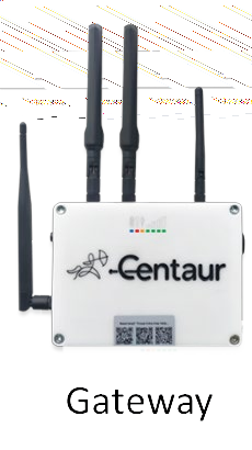
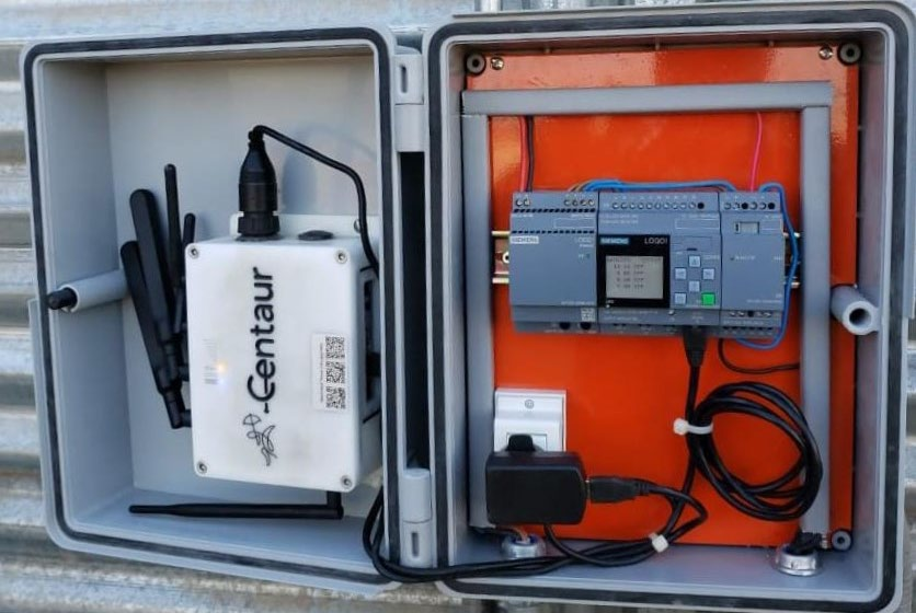
The Centaur Gateway is the central communication node linking all smart sensors, wireless repeaters, and PLC controllers to the Centaur Cloud via cellular or Wi-Fi connectivity.
It relays sensor data to the Internet-of-Crops® platform and receives control commands for aeration, alerts, and analytics.
1.2 Pre-Installation Checks
Before proceeding:
-
Confirm that all components (gateway, sensors, repeaters, PLCs) appear on the Centaur Cloud Platform at https://cloud.centaur.ag.
-
Power on each unit to verify LED status and connectivity.
1.3 Mounting the Gateway
-
Mount the gateway inside a sealed electrical enclosure, ideally co-located with the PLC.
-
Select a box large enough to accommodate the gateway, power supply, cabling, and airflow clearance.
-
Route antennas through weatherproof cable glands and orient them vertically for optimal signal reception.
-
Use the supplied mounting brackets to secure the unit to the enclosure wall.
1.4 Network Configuration
-
For cellular connectivity, insert a SIM card with an active data plan.
-
For Ethernet or Wi-Fi, connect to the nearest access point or local router as per the facility network layout. For a specific Wi-Fi connection, contact the Centaur Support Team.
-
Verify the gateway’s indicator LEDs:
-
Power (yellow) – steady ON
-
XBee (blue) – flashing indicates communication
-
Signal bars (green) – steady sequence indicates good connectivity
-
2. Installing and Turning On Smart Sensors
2.1 Component Description
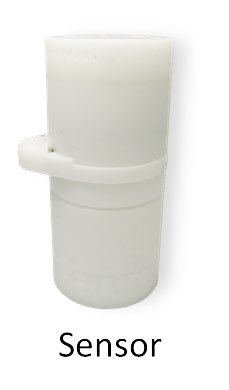
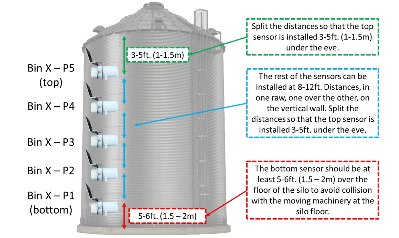
Each bin includes a few wireless quality-monitoring sensors, vertically aligned on one side of the bin wall. Sensors measure internal conditions such as temperature, humidity, and CO₂ /O₂ concentrations to support predictive analytics.
2.2 Placement Guidelines
-
Select the side of the bin with a ladder or easy access for periodic maintenance.
-
Sensors are installed using existing bolts and nuts—no drilling required.
-
Maintain vertical spacing of 3–8 ft (1–2.5 m) between adjacent sensors.
-
The lowest sensor should be 1.5–2 m above the floor to prevent contact with moving equipment.
-
The highest sensor should be 1–1.5 m below the roof eave for accurate readings in the upper grain layer.
2.3 Activation Procedure
-
Using the magnetic activation ring, turn each sensor counter-clockwise to ON.
-
Wait for a short beep and LED flash confirming activation.
-
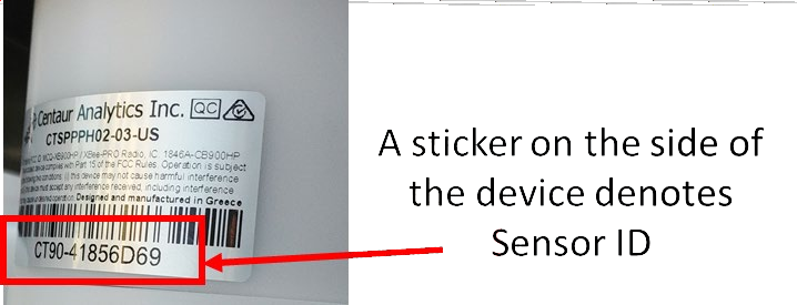
Confirm sensor visibility on cloud.centaur.ag.
2.4 Mounting Procedure
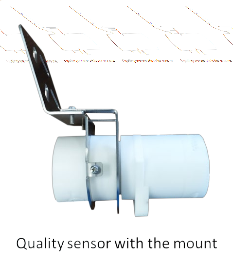
-
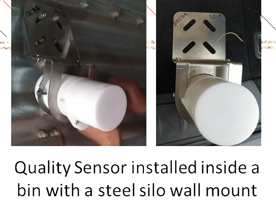
Align the steel wall mount bracket with existing bolts on the corrugated panel.
-
Secure the mount firmly using locknuts; avoid overtightening.
-
Slide the sensor body into the mount until locked.
-
Inspect for a snug fit and clean the surrounding surface to prevent corrosion.
3. Installing Wireless Repeaters
3.1 Function and Quantity
Each installation may include external repeaters and Wi-Fi access points that form the wireless backbone between gateways and PLCs across bins.
-
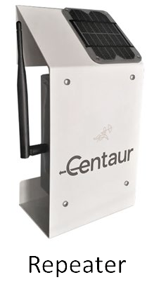
Repeaters: Extend the proprietary Centaur sensor network to ensure stable connectivity across metallic bin structures.
-
Wi-Fi access points: Interconnect PLCs for distributed control and data exchange.
3.2 Placement and Role Assignment
-
Install repeaters just outside the silos, near the side where most sensors are mounted. Contact Centaur Support for further installation instructions tailored to your specific requirements
-
For PLC Wi-Fi repeaters:
-
Designate one as the Coordinator (managing network traffic).
-
The other(s) operate as Clients.
-
Stickers should indicate these roles clearly.
-
3.3 Power and Orientation
-
Power each repeater using the power button located on the side of the device.
-
Orient the antenna vertically, ensuring a clear line of sight to both gateway and nearby sensors.
-
Verify operation by listening for the activation tone consisting of two short audible signals.
4. Setting Up an Aeration Automation PLC
4.1 Overview
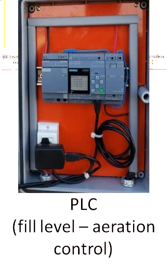
Each Siemens Logo! PLC manages:
-
up to 8 fill-level radar sensors (depending on the installation layout), and
-
up to 20 aeration relays controlling the fans.
Three PLCs coordinate aeration across the system via Wi-Fi interlinks.
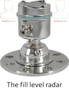
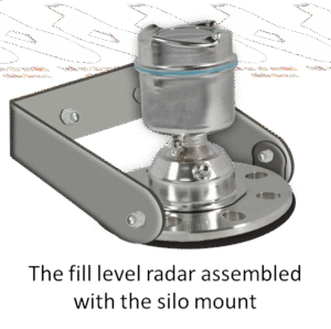
4.2 Installing the Fill Level Radar
-
Mount the radar on the highest point of the silo cylinder (eave top) or roof edge, using the provided silo mounting structure.
-
Run the electrical cable through a steel spiral or steel tube conduit for protection.
-
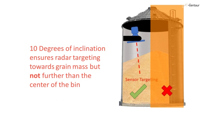
Set the radar angle downward toward the bin center but not beyond it; approximately 10° inclination ensures accurate grain-mass targeting.
4.3 Electrical Integration
-
Mount the PLC in the same electrical box as the gateway.
-
Connect the fill-level radar cable to the dedicated radar interface on the PLC main unit.
-
Wire expansion modules to relay terminals for fan on/off control.
-
Label all ports clearly (e.g., BIN1 FAN1, BIN1 FAN2).
-
Supply 24 V DC power using the provided PSU and verify input voltage.
4.4 Commissioning and Verification
-
Power on PLC and the gateway.
-
Verify radar interface and relays through the Siemens Logo! interface.
-
Ensure the PLC dashboard displays fan and radar status.
-
Test remote visibility on the Centaur Cloud.
-
Record final IP or device ID assignments for reference.
4.5 PLC Component Summary
Each Siemens Logo! PLC system includes :
-
Main Unit – Base controller with logic programming.
-
Power Supply – 24 V DC input.
-
Radar Interface – Dedicated port for level radar integration.
-
Expansion Modules – Additional relay and I/O control for aeration fans.
Support
For additional technical assistance: